Waste readout: Replace the Hyundai/Kia Accent 1.6 L timing belt, rollers and water pump
Lean time study of a 57-minute real-time head-camera recording, measured continuously by the pipeline.
Work time = recorded time minus 0.0 min of filming (talking to or showing things to the camera), which is not part of the process. 7% of windows are low-confidence classifications (marked below).
Top findings
- Waste accounted for 18.4% of the 57.1-minute job, with transport the largest waste category at 5.2 minutes. Stage tools, parts trays, the drain pan and required fluids near the vehicle to reduce trips and handling.
- Necessary non-value-added work accounted for 65.2% of work time, including 16.3 minutes for access and 11.9 minutes for setup. Review the removal/refitting sequence and standardize job preparation to reduce this support effort.
- Correcting the replacement water pump’s mounting-hole fit caused a 90-second rework episode. Compare the replacement pump with the removed pump before trial fitting and obtain a correctly fitting part if they do not match.
Timeline
Top lane: the whole job, moment by moment, by class. Lanes below: where each category occurs. Vertical lines mark the phases of the procedure; hover for times.
Time per step
Waste by type
Necessary non-value-added by type
Hands
Share of the recorded time with both hands, one hand or neither hand working on the job (manipulating or holding steady), from the per-hand annotation.
| Hand | Manipulating | Holding steady | Idle | Out of view | Detected by the hand tracker |
|---|---|---|---|---|---|
| Left | 43% | 32% | 2% | 22% | 44% |
| Right | 63% | 12% | 3% | 22% | 45% |
Hand tracker (open-vocabulary detector at 10 fps, linked into a left and a right track): both hands in view 30% of the time, no hand in view 41%.
Tools
108 tool changes (the tool in hand differs from the previous tool used). Time each tool was in use:
Rework loops
| When | What was redone | Kind | Confidence |
|---|---|---|---|
| 24:45 → 25:30-27:00 | Trial-fitted replacement water pump is removed, its mounting holes are enlarged, and the same pump is refitted and adjusted. | undo redo | 0.99 |
| 32:27 → 32:33-32:36 | The same timing-belt tensioner assembly is positioned again at its engine mounting point after checking the upper mounting feature, then its mounting fastener is threaded. | repeat | 0.87 |
Top 10 waste episodes
| # | Still | What happened | Improvement |
|---|---|---|---|
| 1 | 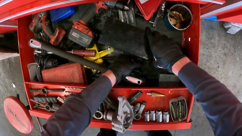 25:30-27:00 · 90 s · step 24 | Rework / redo The mechanic removed the trial-fitted replacement water pump, compared its mounting holes with the old pump using drill bits, and enlarged two holes with a cordless drill. The modified pump was then returned to the engine and refitted. | Before trial fitting, compare the replacement pump’s flange and mounting holes with the removed pump and mounting fasteners. Obtain a correctly fitting replacement if they do not match, avoiding corrective drilling and refitting. |
| 2 | 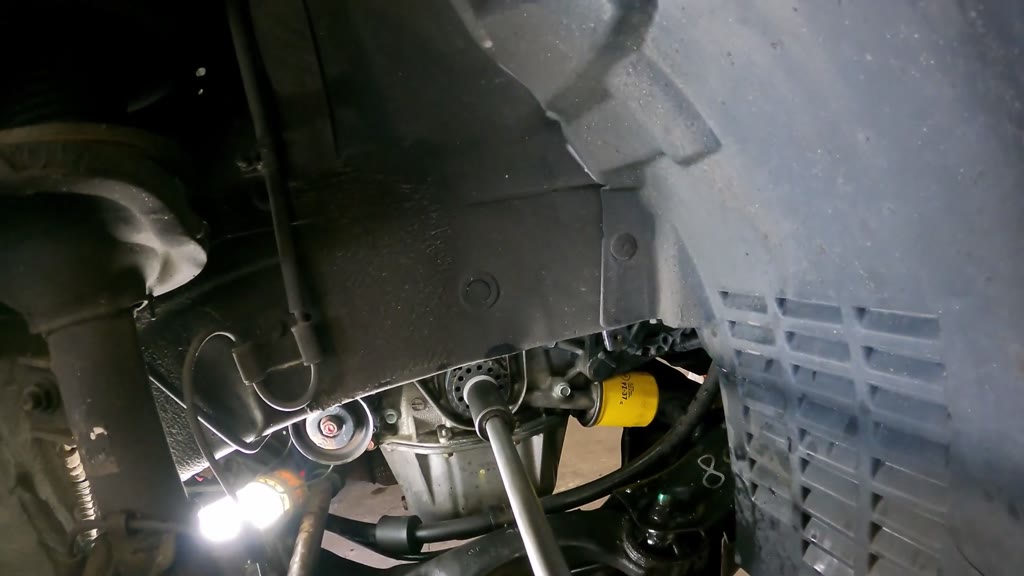 36:33-36:51 · 18 s · step 29 | Waiting / idle The crankshaft socket drive remained in place for about 18 seconds with no work occurring. It was then withdrawn, followed by selection of a cordless ratchet and socket. | Stage the cordless ratchet and socket before the manual rotation check, and make removal of the manual drive the next step once verification is complete. |
| 3 | 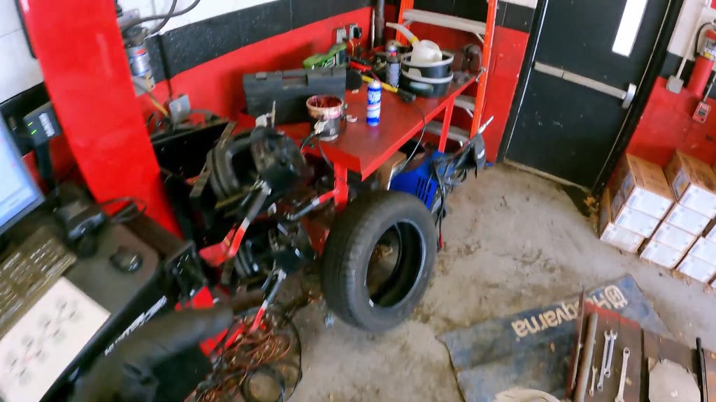 54:42-55:00 · 15 s · step 42 | Transport The mechanic returned the impact wrench, stowed a long pry bar, and carried a liquid jug to the rear workbench. The jug was then positioned for filling. | Fill the required liquid jug during job preparation and stage it on the service cart, eliminating the separate refill trip after wheel installation. |
| 4 | 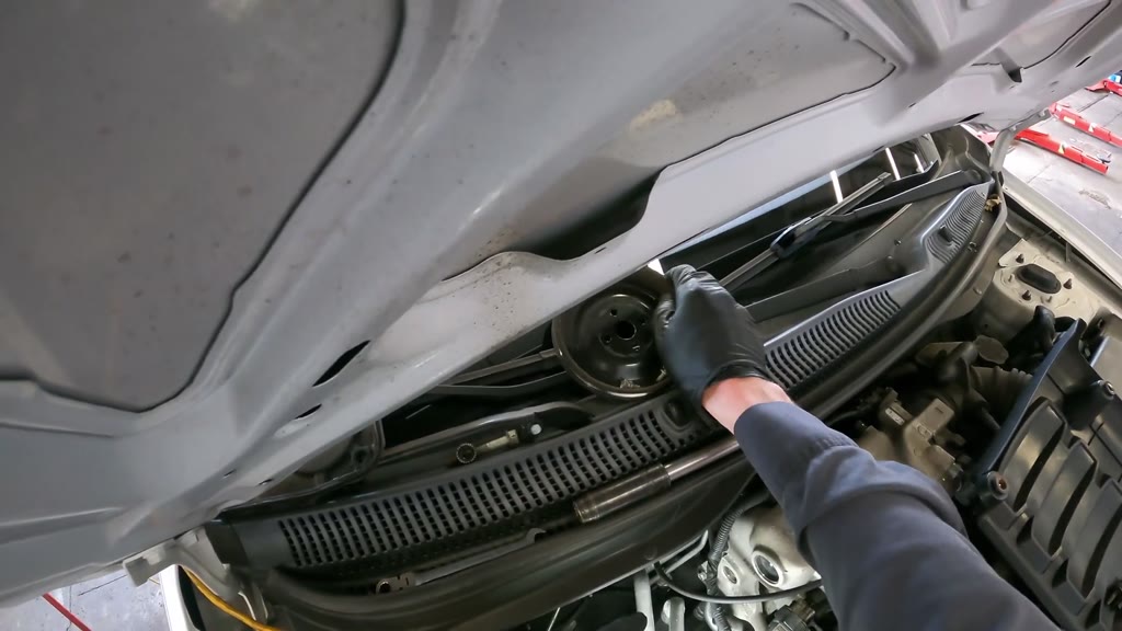 5:57-6:18 · 12 s · step 7 | Transport The mechanic moved the removed accessory pulleys and belts onto the windshield cowl in several separate handling actions. | Place a labeled parts tray within easy reach beside the engine so each pulley and belt can be deposited directly as it is removed. |
| 5 | 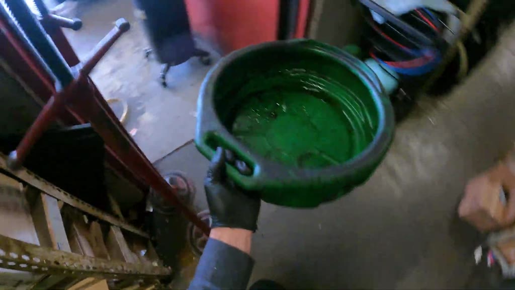 14:48-14:57 · 9 s · step 18 | Transport The mechanic retrieved a green drain pan from storage and carried it through the shop to the car’s front bumper. | Stage the drain pan at the front of the vehicle during job setup, outside the walking path, so it is ready when radiator draining begins. |
| 6 | 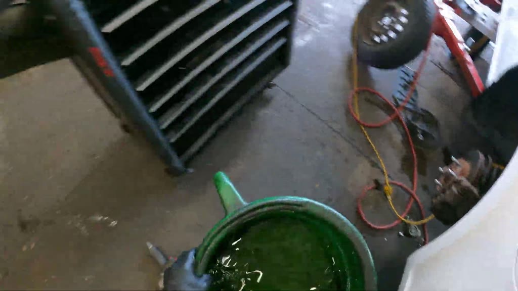 27:21-27:30 · 9 s · step 25 | Transport The mechanic lifted the filled green drain pan and carried it through the shelving aisle to the waste-fluid tank. The pan and tank inlet were then positioned for disposal. | Use a wheeled coolant drain collector that can be rolled to the waste-fluid tank, avoiding the hand-carry of a filled pan. |
| 7 | 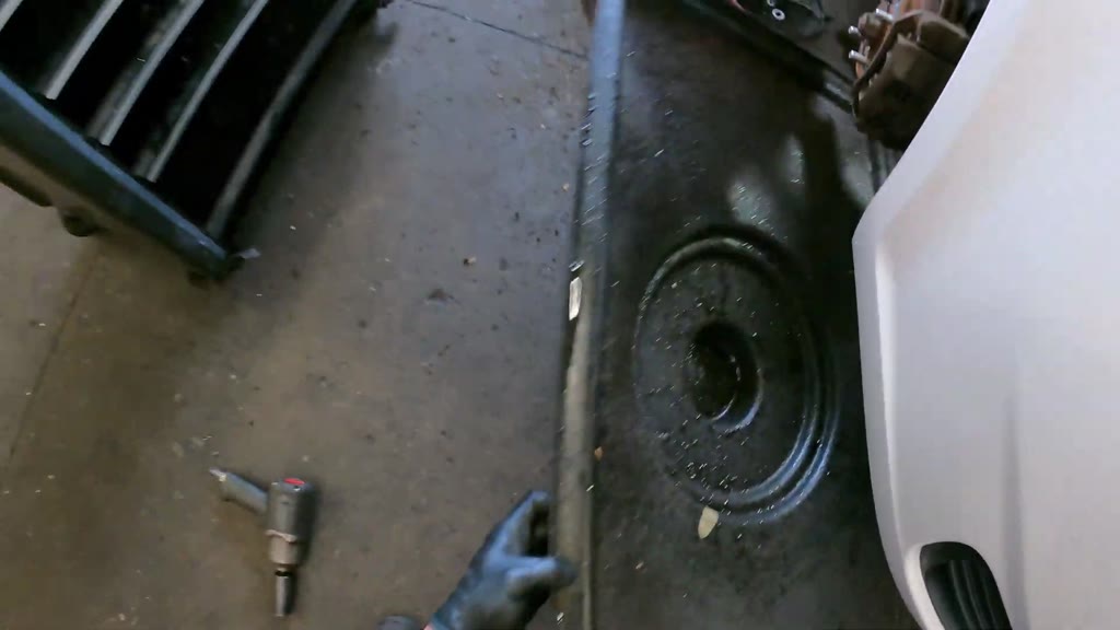 27:09-27:18 · 9 s · step 25 | Transport The mechanic stopped working at the pump to carry a large drain tray to storage. A support stand was moved aside before the tray was stored upright. | Provide a dedicated drain-tray parking slot near the bay, clear of support stands and walkways, to shorten the storage trip and eliminate obstacle handling. |
| 8 | 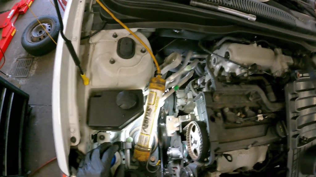 42:36-42:57 · 9 s · step 34 | Transport The mechanic returned the inspection probe to the tool drawer, then retrieved the upper timing cover and its mounting hardware separately from the cowl. | Stage the upper timing cover and its fasteners together in a labeled tray beside the engine before the final timing-reference inspection. |
| 9 | 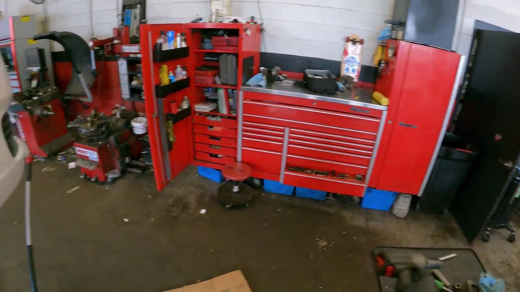 37:42-37:51 · 9 s · step 29 | Transport The mechanic placed the impact wrench on the cart and brought the lower timing cover from the floor toward the engine. | Keep the lower timing cover on the nearby service cart rather than the floor, ready to pick up when the impact wrench is returned. |
| 10 | 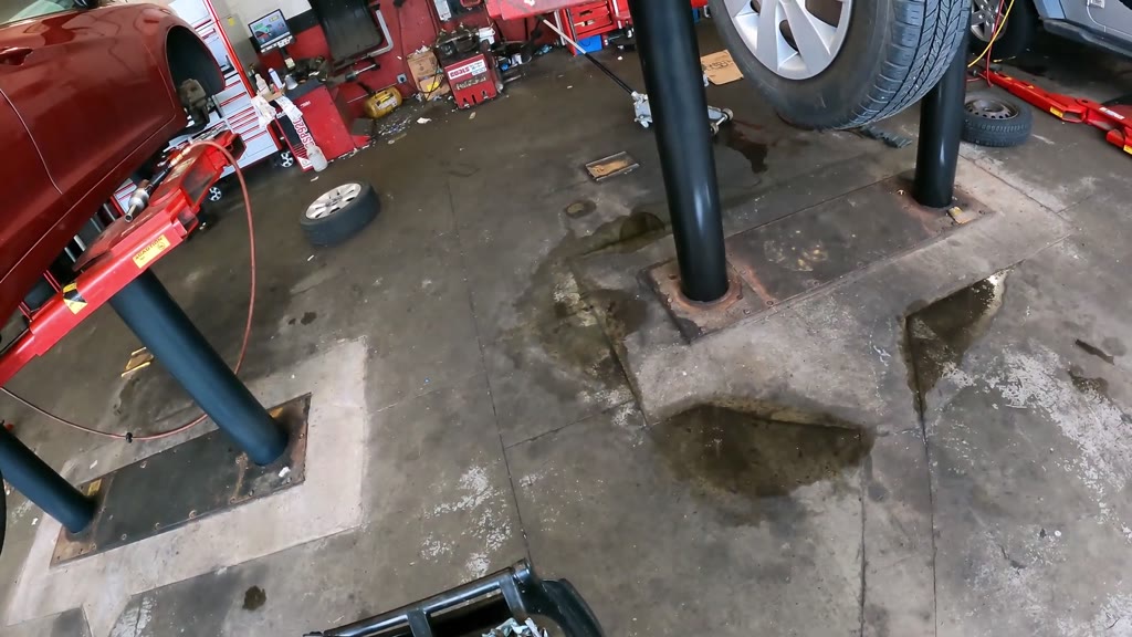 40:33-40:48 · 9 s · step 32 | Waiting / idle There was a brief pause with no recorded work before the mechanic operated the lift control. Another idle interval occurred while the vehicle descended. | Make lowering the vehicle the next defined step after the lower-drive inspection, reducing the pause before lift operation while retaining required control and clearance checks. |
Per-step table
Show the numbers behind the step chart
| Step | Value-added | Necessary | Waste | Filming | Total |
|---|---|---|---|---|---|
| 1. Stage the timing-service parts and support the engine | 0 s | 18 s | 6 s | 0 s | 0:24 |
| 2. Remove the DOHC 16V engine trim cover | 0 s | 24 s | 3 s | 0 s | 0:27 |
| 3. Remove the upper engine-mount bridge bracket | 0 s | 69 s | 6 s | 0 s | 1:15 |
| 4. Remove the timing-cover brace | 0 s | 27 s | 3 s | 0 s | 0:30 |
| 5. Remove the upper timing-belt cover | 0 s | 30 s | 6 s | 0 s | 0:36 |
| 6. Move the power-steering pump and reservoir aside | 0 s | 69 s | 0 s | 0 s | 1:09 |
| 7. Remove the upper accessory pulleys and belts | 0 s | 105 s | 24 s | 0 s | 2:09 |
| 8. Loosen the engine-side bracket attachments | 0 s | 33 s | 3 s | 0 s | 0:36 |
| 9. Remove the timing-side front wheel | 0 s | 21 s | 6 s | 0 s | 0:27 |
| 10. Remove the engine-side splash panel | 0 s | 33 s | 3 s | 0 s | 0:36 |
| 11. Remove the crankshaft accessory pulley | 0 s | 99 s | 18 s | 0 s | 1:57 |
| 12. Remove the lower timing-belt cover | 0 s | 57 s | 6 s | 0 s | 1:03 |
| 13. Turn the connected timing drive and inspect sprocket positions | 0 s | 36 s | 3 s | 0 s | 0:39 |
| 14. Remove the timing-belt idler roller | 66 s | 24 s | 9 s | 0 s | 1:39 |
| 15. Remove the timing-belt tensioner and spring | 21 s | 12 s | 3 s | 0 s | 0:36 |
| 16. Remove the radiator pressure cap | 3 s | 6 s | 0 s | 0 s | 0:09 |
| 17. Remove the timing belt | 3 s | 3 s | 3 s | 0 s | 0:09 |
| 18. Drain the radiator | 0 s | 30 s | 30 s | 0 s | 1:00 |
| 19. Release the water-pump mounting fasteners | 105 s | 222 s | 48 s | 0 s | 6:15 |
| 20. Remove the water pump and old gasket | 9 s | 12 s | 12 s | 0 s | 0:33 |
| 21. Extract residual liquid from the pump cavity | 0 s | 33 s | 15 s | 0 s | 0:48 |
| 22. Clean and dry the water-pump mounting area | 0 s | 39 s | 6 s | 0 s | 0:45 |
| 23. Coat and position the replacement water-pump gasket | 42 s | 18 s | 0 s | 0 s | 1:00 |
| 24. Correct the replacement water-pump mounting-hole fit | 39 s | 9 s | 90 s | 0 s | 2:18 |
| 25. Seat the replacement pump and start its mounting fastener | 39 s | 21 s | 36 s | 0 s | 1:36 |
| 26. Secure the replacement water pump | 54 s | 27 s | 12 s | 0 s | 1:33 |
| 27. Fit the timing belt to the camshaft sprocket and install the idler | 45 s | 39 s | 21 s | 0 s | 1:45 |
| 28. Install and adjust the timing-belt tensioner assembly | 117 s | 63 s | 36 s | 0 s | 3:36 |
| 29. Turn the timing drive manually and recheck its hardware | 18 s | 72 s | 48 s | 0 s | 2:18 |
| 30. Install the lower timing-belt cover | 0 s | 48 s | 9 s | 0 s | 0:57 |
| 31. Install the crankshaft guide plate, pulley and belt | 0 s | 45 s | 6 s | 0 s | 0:51 |
| 32. Adjust the lower accessory-drive hardware | 0 s | 57 s | 9 s | 0 s | 1:06 |
| 33. Lower the vehicle for upper-engine access | 0 s | 45 s | 9 s | 0 s | 0:54 |
| 34. Secure the upper timing-side hardware and inspect the references | 0 s | 57 s | 15 s | 0 s | 1:12 |
| 35. Install the upper timing-belt cover | 0 s | 45 s | 9 s | 0 s | 0:54 |
| 36. Install the shared-hub accessory pulleys and belts | 0 s | 228 s | 18 s | 0 s | 4:06 |
| 37. Secure and check the accessory pump and belt hardware | 0 s | 120 s | 21 s | 0 s | 2:21 |
| 38. Install the upper engine-mount bracket and remove temporary support | 0 s | 60 s | 12 s | 0 s | 1:12 |
| 39. Install the DOHC 16V engine trim cover | 0 s | 39 s | 6 s | 0 s | 0:45 |
| 40. Fit the coolant funnel and begin filling | 0 s | 45 s | 9 s | 0 s | 0:54 |
| 41. Install the wheel-well splash panel | 0 s | 48 s | 12 s | 0 s | 1:00 |
| 42. Install the front wheel, wheel cover and lug nuts | 0 s | 42 s | 12 s | 0 s | 0:54 |
| 43. Continue filling and clear the working area | 0 s | 54 s | 21 s | 0 s | 1:15 |
| 44. Start the engine and observe the coolant funnel | 0 s | 12 s | 6 s | 0 s | 0:18 |
| 45. Secure the engine-cover bolt beside the intake hose | 0 s | 24 s | 0 s | 0 s | 0:24 |
| 46. Remove the coolant funnel and reinstall the radiator cap | 0 s | 14 s | 0 s | 0 s | 0:14 |
Method and caveats
- The pipeline watched the recording at one frame per second and wrote, at every critical change, the main action (verb, object, tool, contact, state change), what each hand was doing, and the procedure step. Each moment was then classified into one lean category from that description and from the hand tracker's numbers (how much each hand was in view and moving).
- Categories: value-added (work on the parts the job replaces: removing the worn ones, fitting, aligning and tensioning the new ones); necessary non-value-added (access: removing and refitting other parts to reach the work; setup; positioning; checks); waste (waiting/idle, searching, extra motion, transport, rework, defects, overprocessing); and filming, which is excluded from work time.
- These are machine estimates with no human ground truth. Category boundaries are judgement calls (e.g. walking to fetch a tool is transport or extra motion); 7% of moments are marked low-confidence. Treat the percentages as indicative (a few points either way), and use the top-10 table with its timestamps to check the episodes that matter in the video.
- Time is divided into short slices, so very brief events take the category of the slice they fall in.
- One recording of one worker is not a standard time; it shows where time went on this job.