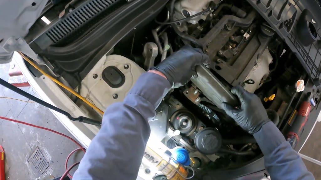
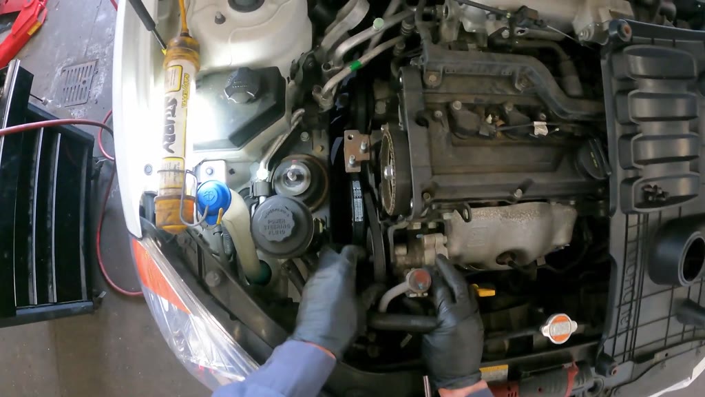
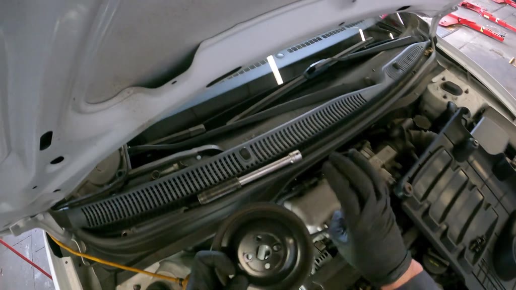
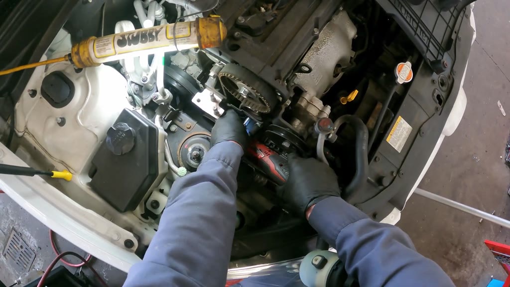
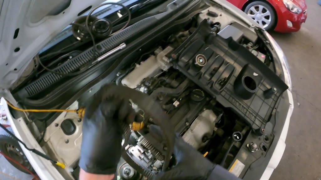
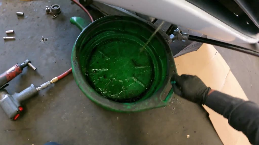
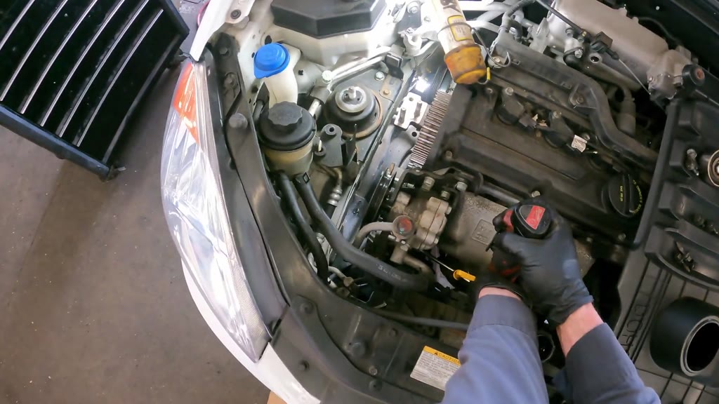
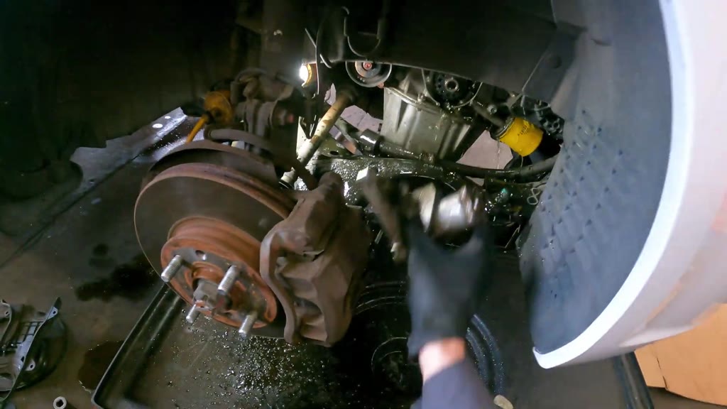
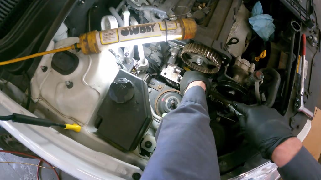
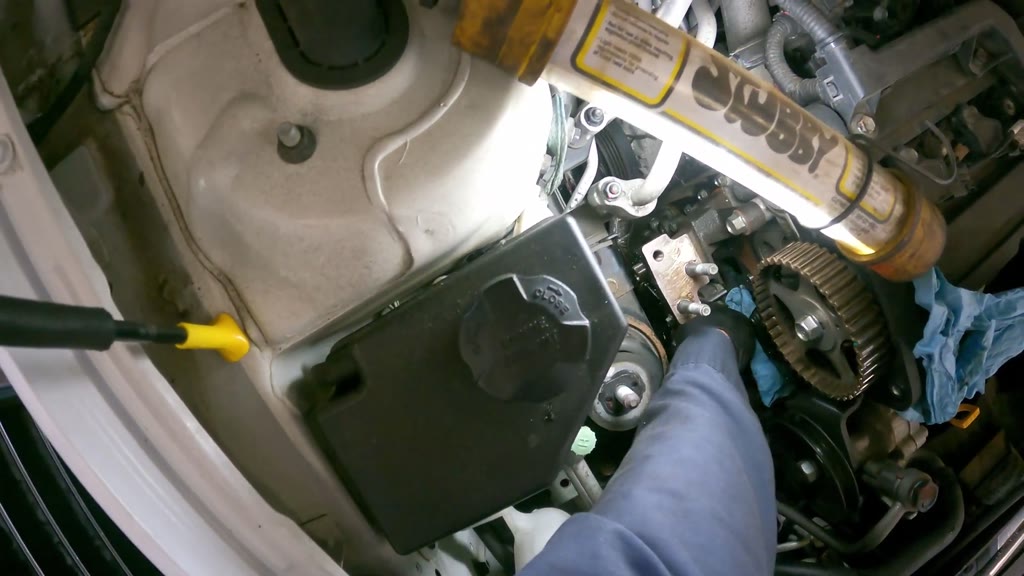
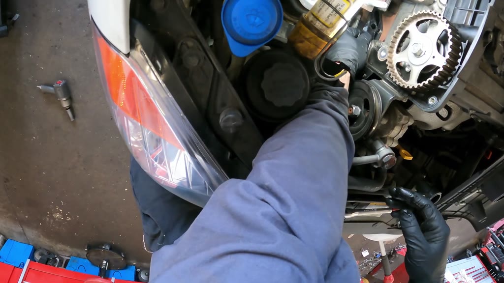
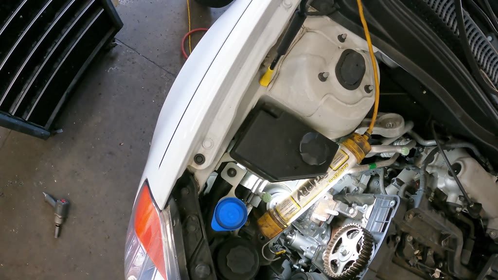
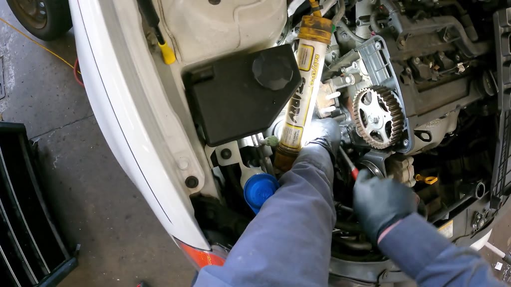
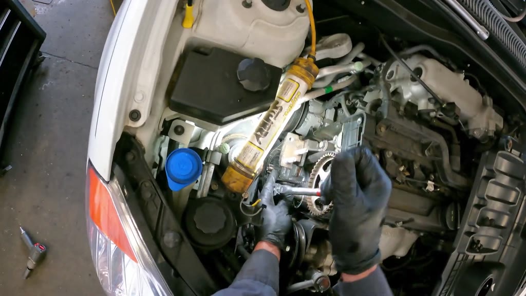
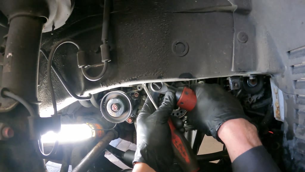
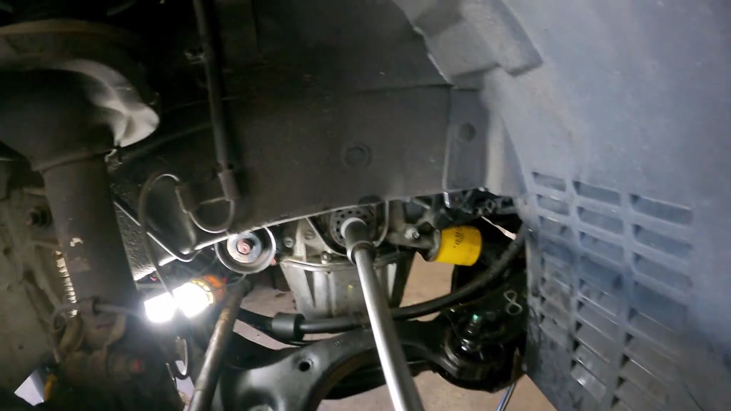
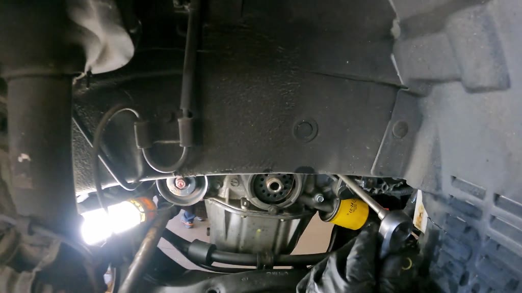
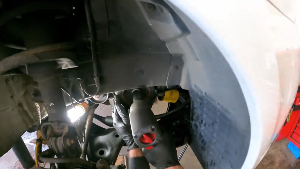
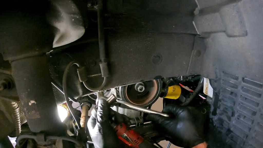
Replace the Hyundai/Kia Accent 1.6 L timing belt, rollers and water pump
Procedure guide written by the pipeline from a 57-minute head-camera recording of the job, performed in real time.
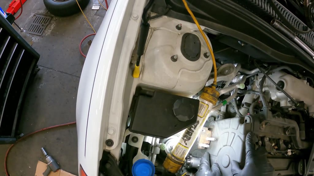
Steps46
Recorded job time57 min 05 s
Phases8
Tools36
Parts40
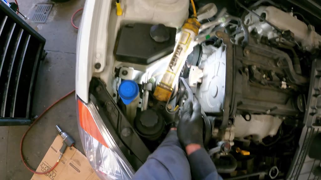
Overview
Open the timing-side engine and wheel-well access, then remove the accessory drive components, timing covers, belt and rollers. Drain the cooling system, remove the water pump, and prepare and install the replacement pump and gasket. Fit the timing belt and rollers, turn the drive manually, and inspect the belt seating and timing references before reassembly. Restore the mount, covers and wheel, refill through a coolant funnel, and check engine operation and the funnel liquid surface.
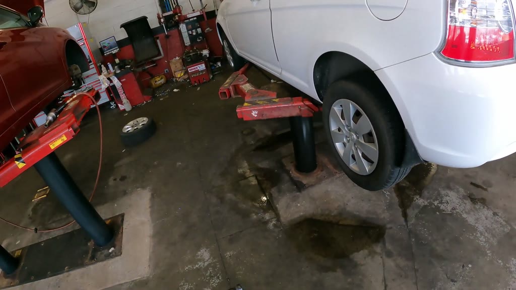
Equipment: Use this procedure for the transverse Hyundai/Kia Accent 1.6 L DOHC 16V four-cylinder engine in a Hyundai passenger car. Use the shop vehicle lift for wheel-well access and a blocked floor jack for temporary engine support.
Phase
Steps
Time
Prepare and strip upper-engine access
1-8
7 min 05 s
Open the lower drive and remove the timing belt
9-17
7 min 15 s
Drain the cooling system and remove the water pump
18-21
8 min 36 s
Prepare and install the replacement water pump
22-26
7 min 10 s
Install and check the timing belt and rollers
27-29
7 min 41 s
Reassemble the timing and accessory drives
30-37
12 min 19 s
Restore the mount, covers and wheel
38-42
4 min 45 s
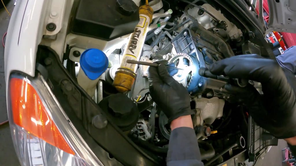
Finish filling and check engine operation
43-46
2 min 14 s
Tools
Floor jack
Wooden support block
Vehicle lift
Small pneumatic impact wrench
Pneumatic impact wrench
Air hose
Sockets
Socket extensions
Cordless ratchet
Manual ratchet
Long socket-drive tool
Combination wrench
19 mm combination wrench
Tube work light
Flashlight
Screwdriver
Flat pry bar
Long-nose pliers
Thin metal probe
Cardboard floor pad
Drain pan
Wide drain tray
Fluid extractor
Shop towels
Disposable gloves
Aerosol cleaner
Blow gun
Gasket-compound dispenser
Twist drill bits
Cordless drill
Waste-fluid receiver
Red-compound applicator
Coolant funnel kit
Liquid jug
Fluid dispensing nozzle
Ignition key
Parts and materials
Timing belt × 1 Remove the existing belt and fit the prepared toothed belt.
Timing-belt idler roller × 1 Replace the roller beneath the camshaft sprocket with the green-sealed roller.
Timing-belt tensioner roller and bracket × 1 Replace the spring-loaded assembly with the blue-sealed roller and slotted bracket.
Tensioner spring × 1 Unhook during removal and position at the replacement tensioner bracket.
Water pump × 1 Remove the existing pump, compare mounting-hole fit, and install the prepared replacement.
Water-pump gasket × 1 Remove the old gasket and position the compound-coated replacement on the engine.
Black gasket compound Apply and spread on one face of the replacement pump gasket.
Water-pump mounting bolts Retain recovered hardware and start the replacement pump fasteners by hand.
DOHC 16V engine trim cover × 1 Remove for access and refit around the oil-cap opening and adjacent hoses.
Engine trim-cover mounting bolts × 4 Retain the four removed attachments; complete the hose-side attachment during final checks.
Upper engine-mount bridge bracket × 1 Remove while the engine is supported and refit to the engine and round body-side mount.
Engine-mount bracket hardware Hand-start the three engine-side fasteners and the body-side center nut during reassembly.
Timing-cover brace × 1 Remove the narrow metal brace and retain it with its hardware.
Timing-cover brace bolts × 2 Remove the attachments at both ends of the brace.
Upper timing-belt cover × 1 Remove to expose the camshaft sprocket and refit its outer- and inner-edge attachments.
Lower timing-belt cover × 1 Remove through the wheel well and refit the lower and two upper mounting bolts.
Timing-cover mounting hardware Keep the upper- and lower-cover hardware with the corresponding cover.
Power-steering pump × 1 Move from its bracket position without disconnecting its hoses.
Power-steering fluid reservoir × 1 Lift from its bracket and keep capped while moving it aside.
Power-steering reservoir hoses × 2 Guide aside without disconnecting them.
Accessory-drive belts × 3 Retain each removed belt with its pulley route and refit the belt loops during reassembly.
Smaller stepped accessory pulley × 1 Remove by hand and refit to the exposed shared hub.
Larger dished accessory pulley × 1 Remove by hand and refit over the shared-hub pulley assembly.
Accessory-pulley mounting bolts × 4 Hand-start and tighten the four bolts around the shared hub.
Short pulley-area fastener × 1 Select and hand-start at the smaller pulley and hub area.
Crankshaft accessory pulley × 1 Rock off the shaft and refit with its accessory belt.
Crankshaft pulley bolt and washer × 1 Remove the center bolt and apply red compound to its threads before final installation.
Crankshaft-nose ring × 1 Remove the small ring and keep it in the removed pulley center.
Crankshaft belt-guide plate × 1 Fit the dished plate against the sprocket before installing the crankshaft pulley.
Temporary crankshaft-center bolt assembly × 1 Install for manual drive turning and remove before refitting the lower drive.
Red bolt-thread compound Apply to the crankshaft pulley bolt's threaded end.
Engine-side splash panel × 1 Remove through the wheel well and refit the two upper attachments.
Timing-side front wheel and tire × 1 Remove for lower-engine access and refit to the four hub studs.
Hyundai wheel cover × 1 Align with the valve stem and lug openings during installation.
Front-wheel lug nuts × 4 Retain together and hand-thread all four before tool tightening.
Radiator pressure cap × 1 Remove for draining and filling, then reinstall after removing the funnel fittings.
Radiator drain plug × 1 Remove to drain coolant and refit after the initial drain.
Cooling-system refill liquid Add through the mounted funnel in successive pours.
Upper radiator hose × 1 Squeeze while observing the funnel during final filling checks.
Small hose beside the engine-cover edge × 1 Move clear of the final cover-bolt recess and return along the cover edge.
Safety
Before you start
Keep the hood secured with its support rod during engine-bay work.
Support the engine with the blocked floor jack before removing the upper mount bracket, and retain that support until the mount hardware is secured.
Keep clear of the vehicle-lift arms and the descending vehicle when operating the lift.
Let the cooling system cool before removing its pressure cap, and position drain collection equipment before opening coolant joints.
Keep the capped power-steering reservoir upright and avoid pulling or trapping its connected hoses.
Wear gloves for fluid and compound handling, and use eye protection when drilling, spraying cleaner or operating the blow gun.
Keep drained cooling-system liquid in a suitable waste receiver; do not mix it with incompatible waste fluids.
Keep air hoses, lamp leads, loose hardware and liquid patches clear of walking and lower working areas.
Keep hands, hoses, tools and clothing clear of moving accessory belts during engine operation.
Inspect belt seating and timing-reference features without assuming that visual checks establish a measured tension or tightening torque.
Steps
Prepare and strip upper-engine access
Video 0:12
1
Stage the timing-service parts and support the engine
Time taken 22 s · video 0:00-0:22
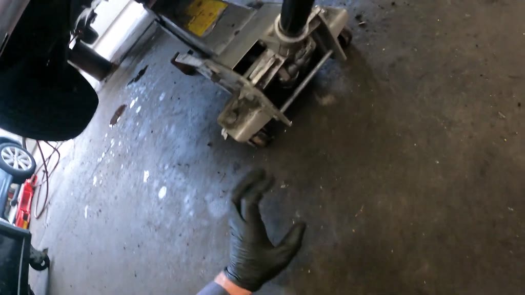
Place the water pump, toothed timing belt and two roller assemblies on the cart work surface. Position the wooden block on the floor-jack saddle, roll the jack beneath the front engine area, and operate its handle to establish temporary support. Leave the jack positioned for the mount-bracket work.
Tools
Floor jackWooden support block
Parts
Water pumpTiming beltTiming-belt idler rollerTiming-belt tensioner roller and bracket
⚠ Establish engine support before removing the mount bracket.
Video 0:42
2
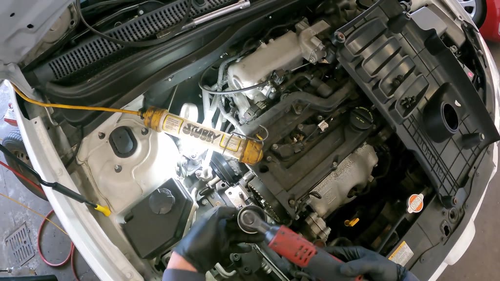
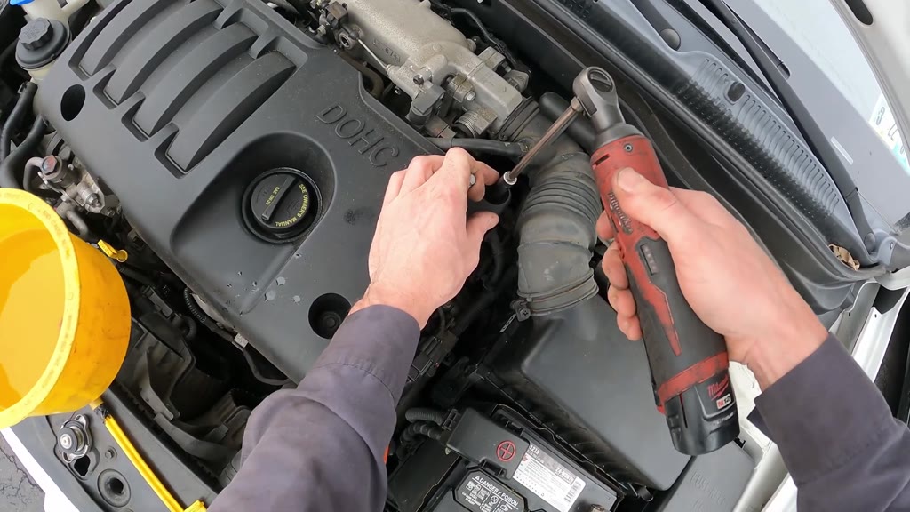
Remove the DOHC 16V engine trim cover
Time taken 26 s · video 0:22-0:48
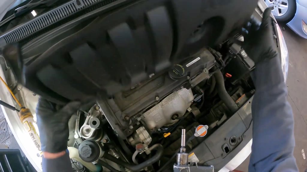
Connect the small pneumatic impact wrench and use its socket to release the cover attachments. Finish the loosened fastener by hand, lift off the cover, and turn it underside-up. Set the cover aside with its four mounting attachments.
Tools
Small pneumatic impact wrenchSocketsAir hose
Parts
DOHC 16V engine trim coverEngine trim-cover mounting bolts
⚠ Keep the loose mounting hardware with the cover.
Video 1:41
3
Remove the upper engine-mount bridge bracket
Time taken 1 min 15 s · video 0:48-2:03
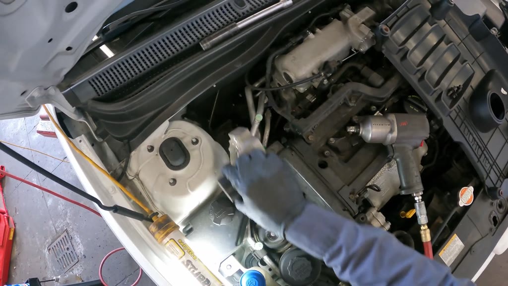
Change to the larger pneumatic impact wrench and release the bracket fasteners, using suitable sockets and an extension for the recessed positions. Lift out the aluminum bridge bracket while leaving the round rubber mount in place. Set the bracket and hardware aside, then illuminate and inspect the cleared timing-side access.
Tools
Pneumatic impact wrenchSocketsSocket extensionsAir hoseTube work light
⚠ Keep the blocked floor jack supporting the engine throughout bracket removal.
⚠ Keep the reservoir capped and upright when nudging it aside.
Video 2:15
4
Remove the timing-cover brace
Time taken 30 s · video 2:03-2:33
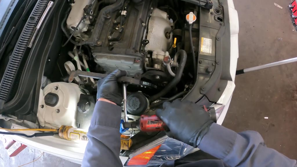
Fit a socket and extension to the cordless ratchet and release the bolts at both ends of the narrow metal brace. Lift the brace away, collect its loose hardware, and place it on the cowl. Reposition the tube light and use the flashlight to inspect the cleared cover edge and lower pulley gaps.
Tools
Cordless ratchetSocketsSocket extensionsTube work lightFlashlight
Parts
Timing-cover braceTiming-cover brace bolts
⚠ Keep the brace hardware together and clear of the engine opening.
Video 2:59
5
Remove the upper timing-belt cover
Time taken 37 s · video 2:33-3:10
Configure the cordless ratchet socket and release the remaining upper-cover attachments. Collect the loose fasteners, lift the cover clear, and set it on the cowl. Check that the camshaft sprocket and upper timing-side area are exposed.
⚠ Retain the cover fasteners with the removed cover.
Video 4:02
6
Move the power-steering pump and reservoir aside
Time taken 1 min 09 s · video 3:10-4:19
Use a combination wrench on the pump pulley's central hex for short turning strokes, then loosen the pump mounting attachments with the cordless ratchet. Move the pump from its bracket position and slip its belt section clear without disconnecting the hoses. Lift the capped reservoir from its bracket and guide its two hoses aside so the accessory-drive space is clear.
⚠ Do not pull, kink or disconnect the attached power-steering hoses.
Video 5:45
7
Remove the upper accessory pulleys and belts
Time taken 2 min 10 s · video 4:19-6:29
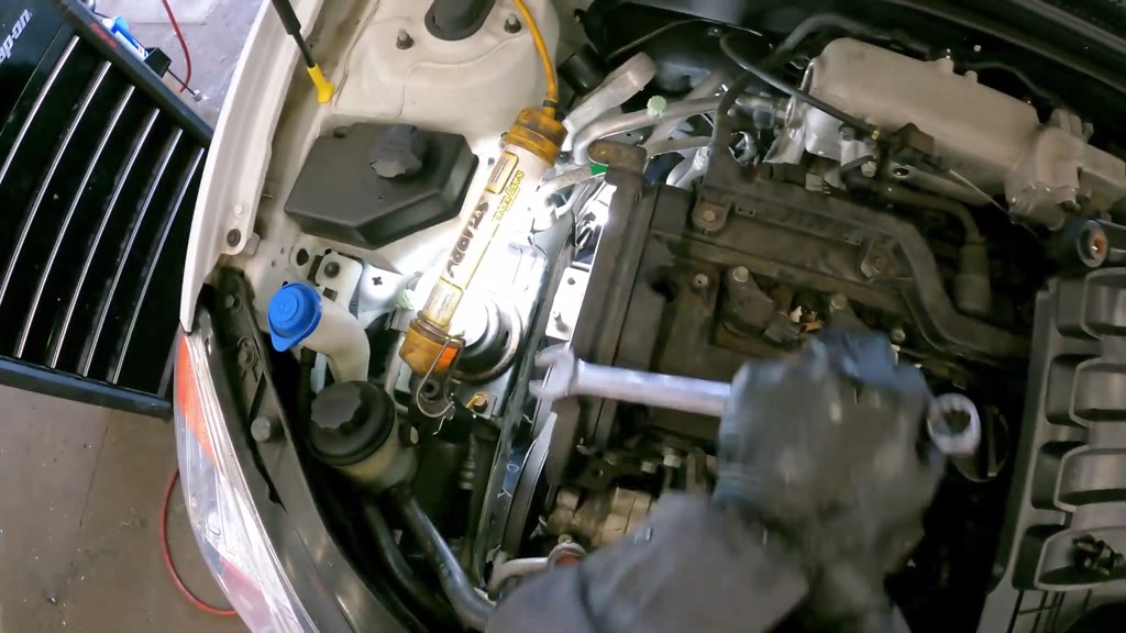
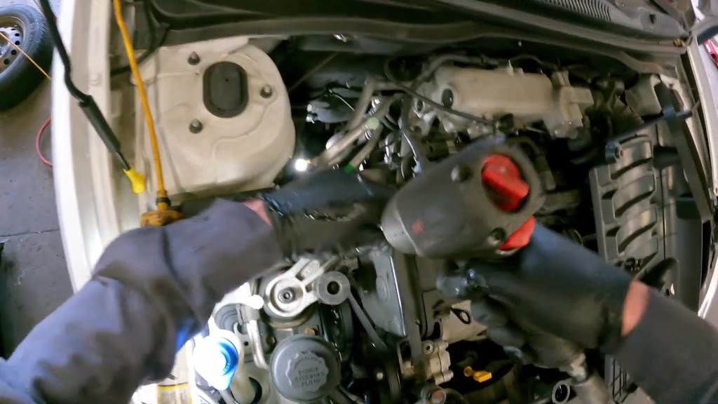
Loosen the lower accessory-drive attachment with the cordless ratchet and short combination-wrench strokes, using the tube light for access. Finish the pulley attachments by hand, lift out the first dished pulley, and remove its loose belt loop. Work the smaller stepped pulley and second belt clear, then place both pulley-and-belt groups on the cowl. Turn the remaining black pulley by hand and inspect the exposed hub with the flashlight.
Tools
Cordless ratchetSocketsCombination wrenchTube work lightFlashlight
⚠ Keep each belt with its corresponding pulley group.
⚠ Collect small pulley fasteners before moving the pulleys away.
Video 6:36
8
Loosen the engine-side bracket attachments
Time taken 36 s · video 6:29-7:05
Use the cordless ratchet and socket at the lower-center attachment below the camshaft sprocket and the upper-left attachment. Continue the loosened upper-left attachment by hand while leaving the bracket in place. Use the flashlight to inspect the bracket, exposed hub and lower accessory-drive access.
Tools
Cordless ratchetSocketsFlashlight
Parts
Engine-side bracket attachments
Open the lower drive and remove the timing belt
Video 7:26
9
Remove the timing-side front wheel
Time taken 25 s · video 7:05-7:30
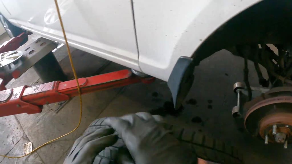
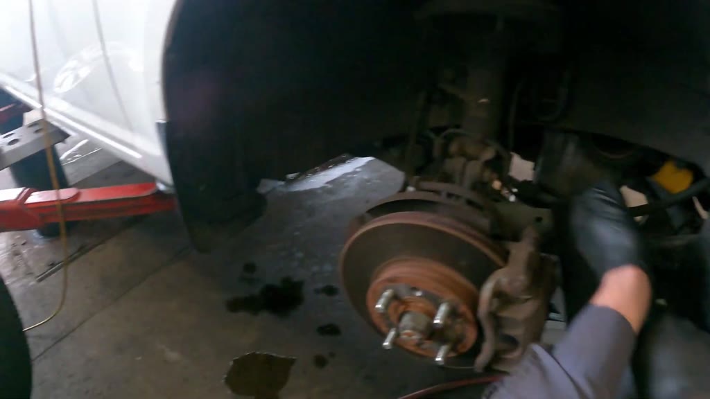
Fit the wheel-fastener socket to the pneumatic impact wrench and remove the four lug nuts. Remove the Hyundai wheel cover and place it with the nuts in the lift area. Grip opposite sides of the tire, pull the wheel off the hub, and inspect the opened wheel well.
Tools
Pneumatic impact wrenchSockets
Parts
Timing-side front wheel and tireHyundai wheel coverFront-wheel lug nuts
⚠ Keep the vehicle supported while removing the wheel.
⚠ Keep the four lug nuts together.
Video 8:01
10
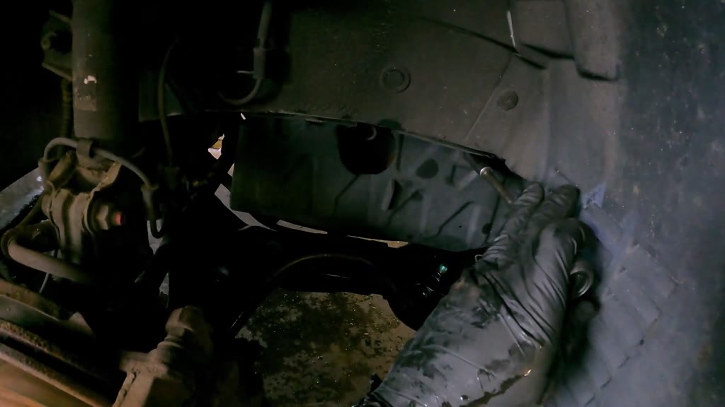
Remove the engine-side splash panel
Time taken 38 s · video 7:30-8:08
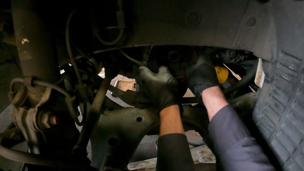
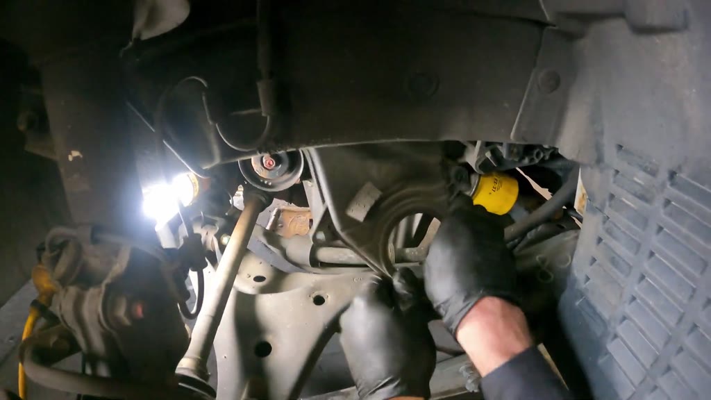
Use the cordless ratchet with a socket extension to release the right-edge, upper and inner panel attachments. Pull the freed molded panel through the wheel opening and set it aside. Inspect the crankshaft-pulley access above the lower control arm.
⚠ Maneuver the panel around the surrounding suspension and liner without forcing it.
Video 9:43
11
Remove the crankshaft accessory pulley
Time taken 1 min 55 s · video 8:08-10:03
Adjust the floor jack, then remove the crankshaft-pulley center bolt with the pneumatic impact wrench. Work the recessed attachment above-left of the pulley with manual and powered socket tools, and position an additional tube light beside the strut. Rock and pull the pulley off by hand while freeing the surrounding accessory belt. Remove the small shaft-area ring and keep it in the pulley center.
Crankshaft accessory pulleyCrankshaft pulley bolt and washerCrankshaft-nose ringAccessory-drive belts
⚠ Retain the temporary engine support while adjusting lower access.
⚠ Keep the small shaft ring and center bolt with the pulley.
Video 10:39
12
Remove the lower timing-belt cover
Time taken 1 min 04 s · video 10:03-11:07
Reposition the tube light and check socket access to the lower-cover attachments. Release the lower-center and two recessed upper fasteners with the cordless ratchet, finishing the accessible fastener by hand. Maneuver the cover around the crankshaft opening and out through the wheel well, then inspect the exposed sprocket, belt and surrounding reference area with the flashlight.
Tools
Tube work lightCordless ratchetSocketsSocket extensionsFlashlight
⚠ Keep the cover clear of the exposed belt while withdrawing it.
Video 11:22
13
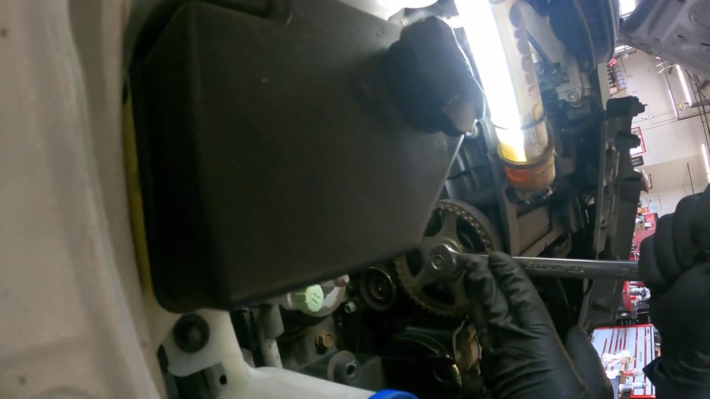
Turn the connected timing drive and inspect sprocket positions
Time taken 40 s · video 11:07-11:47
Engage a combination wrench on the camshaft-sprocket center fastener and make short turning movements with the belt installed. Alternate the turning work with inspection of the crankshaft-sprocket position through the wheel opening. Check the roller and fastening area beneath the camshaft sprocket by hand before releasing the belt hardware.
⚠ Keep the belt fitted while comparing the connected sprocket positions.
⚠ Do not treat this inspection alone as confirmation of final timing alignment.
Video 13:18
14
Remove the timing-belt idler roller
Time taken 1 min 38 s · video 11:47-13:25
Work the recessed timing-drive fasteners above the crankshaft sprocket with manual and cordless ratchets. Release the idler mounting fastener beneath the camshaft sprocket, changing sockets and using the longer manual socket drive as needed. Lift the freed roller out and place it on the detached engine trim.
Tools
Manual ratchetLong socket-drive toolCordless ratchetSocketsSocket extensionsTube work light
Parts
Timing-belt idler rollerIdler mounting fastener
⚠ Support the roller as its mounting fastener releases.
Video 13:52
15
Remove the timing-belt tensioner and spring
Time taken 37 s · video 13:25-14:02
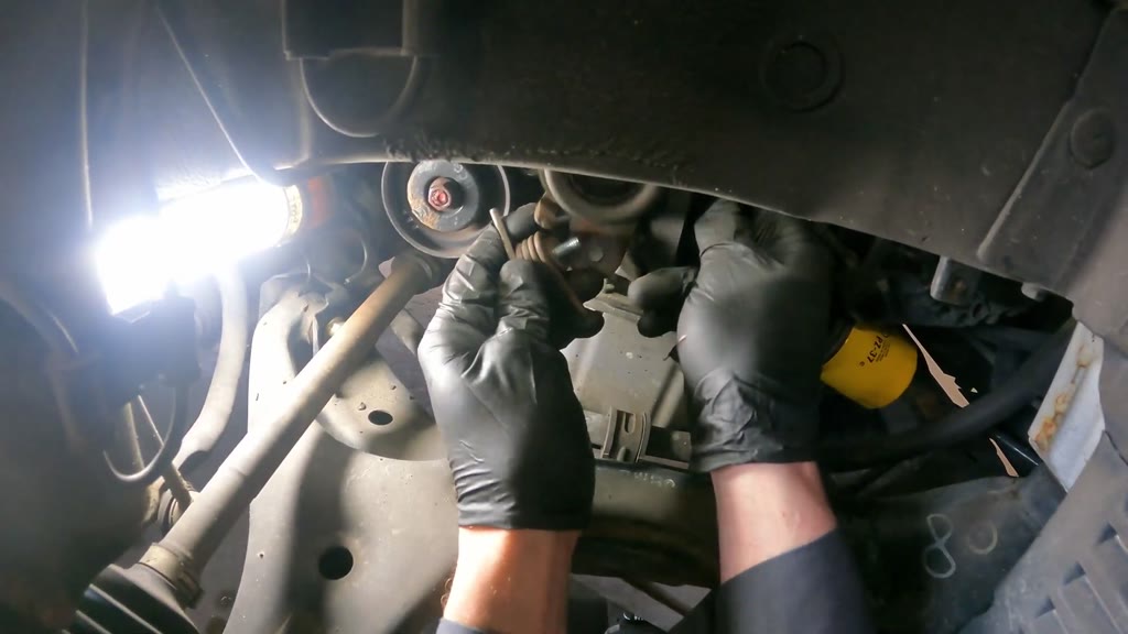
Check the remaining belt and tensioner area by hand, then release the recessed tensioner mounting fastener with the cordless ratchet. Unhook the return spring while supporting the roller and mounting plate. Maneuver the tensioner assembly out and pull the loosened belt run clear near the crankshaft sprocket.
Tools
Cordless ratchetSocketsTube work light
Parts
Timing-belt tensioner roller and bracketTensioner springTiming belt
⚠ Control the spring and support the tensioner while releasing it.
Video 14:06
16
Remove the radiator pressure cap
Time taken 7 s · video 14:02-14:09
Turn the radiator pressure cap by hand and lift it clear of the filler neck. Set it on the radiator-support panel and leave the filler neck open for the cooling-system work.
Parts
Radiator pressure cap
⚠ Let the cooling system cool before opening the pressure cap.
Video 14:12
17
Remove the timing belt
Time taken 11 s · video 14:09-14:20
Slip the loose toothed belt off the camshaft sprocket and the remaining routing by hand. Lift the complete loop clear of the engine and place it on the detached engine trim beside the removed roller.
Parts
Timing belt
⚠ Avoid moving the exposed sprockets independently while the belt is removed.
Drain the cooling system and remove the water pump
Video 15:12
18
Drain the radiator
Time taken 1 min 00 s · video 14:20-15:20
Flatten the cardboard beside the jack for lower access and adjust the jack handle as needed. Position the green drain pan beneath the radiator drain and use the screwdriver to unscrew and withdraw the green plug. Move the pan beneath the flowing coolant and place the removed plug beside the radiator cap.
Tools
Cardboard floor padFloor jackDrain panScrewdriver
Parts
Radiator drain plugDrained coolant
⚠ Position the pan before withdrawing the drain plug.
⚠ Keep the lower working area clear of hoses and liquid spills.
Video 20:31
19
Release the water-pump mounting fasteners
Time taken 6 min 14 s · video 15:20-21:34
Move the connected reservoir down into the front corner, illuminate the pump housing, and release the accessible mounting fasteners with the cordless ratchet, storing recovered bolts on the detached trim. Refit the radiator drain plug with the screwdriver, replace the right-hand glove, and position the wide drain tray over the green pan. Continue releasing the recessed mounting points from above, through the wheel well and from beneath the engine with powered and manual ratchets, sockets and extensions. Hold hoses clear, use the flashlight to check the recesses, and test housing movement with the flat pry bar before checking the pump joint and tray position.
Tools
Tube work lightFlashlightCordless ratchetManual ratchetSocketsSocket extensionsScrewdriverDisposable glovesWide drain trayDrain panFlat pry barCardboard floor pad
⚠ Keep the connected hoses clear without pulling on them.
⚠ Keep the wide tray outlet over the drain pan.
⚠ Use controlled pry-bar pressure at the housing and avoid damaging the mounting face.
⚠ Maintain vehicle and engine support during underside access.
Video 21:44
20
Remove the water pump and old gasket
Time taken 34 s · video 21:34-22:08
Use the flat pry bar to separate the pump joint and let the released coolant drain into the wide tray. Lift the old pump out through the wheel opening and inspect its impeller and shaft hub before setting it aside for disposal. Hold the adjacent hose clear, peel the old gasket from the engine mounting face, and place it beside the replacement pump.
Tools
Flat pry barWide drain tray
Parts
Water pumpWater-pump gasketDrained coolant
⚠ Keep the collection tray beneath the joint before separating it.
⚠ Expect coolant to splash when the joint opens.
⚠ Do not gouge the gasket mounting face.
Video 22:32
21
Extract residual liquid from the pump cavity
Time taken 48 s · video 22:08-22:56
Position the fluid extractor beside the bumper, extend its pickup hose, and connect the air hose after disconnecting it from the impact wrench. Insert the pickup into the open pump cavity and adjust the extractor and inline valve while holding the hose in place. Wipe around the opening and pickup with a shop towel, withdraw the hose, and disconnect and return the extractor.
Tools
Fluid extractorAir hoseShop towels
Parts
Residual cooling-system liquid
⚠ Control the pickup hose so it does not spill residual liquid when withdrawn.
⚠ Disconnect the air coupling before returning the extractor.
Prepare and install the replacement water pump
Video 23:15
22
Clean and dry the water-pump mounting area
Time taken 43 s · video 22:56-23:39
Spray aerosol cleaner across the exposed pump mounting face, cavity and adjacent timing-side surfaces. Wipe the face and recess below the camshaft sprocket with a shop towel. Connect the long-nozzle blow gun, blow around the mounting area, and withdraw and put away the gun when the cleaning work is complete.
Tools
Aerosol cleanerShop towelsBlow gunAir hose
Parts
Water-pump mounting face
⚠ Wear eye protection for aerosol and compressed-air work.
⚠ Keep debris and spray away from your face and the surrounding work area.
Video 24:30
23
Coat and position the replacement water-pump gasket
Time taken 1 min 00 s · video 23:39-24:39
Prepare the compound dispenser and inspect the replacement gasket. Trace black compound around one gasket face, recap the container, and spread the coating around the sealing face with gloved fingertips. Wipe the soiled fingers, inspect the prepared gasket, and orient it at the engine mounting face. Guide it into the recess and press it into position around the mounting face.
Tools
Gasket-compound dispenserShop towelsTube work light
Parts
Water-pump gasketBlack gasket compound
⚠ Keep the prepared sealing face clean while positioning the gasket.
Video 26:44
24
Correct the replacement water-pump mounting-hole fit
Time taken 2 min 18 s · video 24:39-26:57
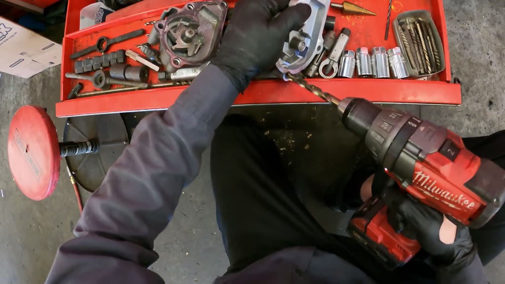
Inspect the replacement pump, turn its shaft by hand, and trial-fit it against the gasket while holding the timing backing cover clear. Withdraw it and compare mounting-hole fit against the removed pump using loose twist drill bits. Fit the selected bit to the cordless drill and enlarge the two existing replacement-pump flange holes, reorienting the pump between holes and making a further pass through the second hole. Withdraw the bit and inspect the modified pump.
Tools
Tube work lightTwist drill bitsCordless drill
Parts
Water pumpWater-pump gasketTiming-drive backing cover
⚠ Compare the replacement and removed pump before modifying the flange holes.
⚠ Hold the pump securely and keep hands clear of the rotating bit.
⚠ Confine drilling to the two existing mounting holes and protect the impeller and sealing face.
⚠ Keep drilling chips out of the engine opening.
Video 28:20
25
Seat the replacement pump and start its mounting fastener
Time taken 1 min 36 s · video 26:57-28:33
Offer the modified pump to the mounting recess, hold the timing backing cover clear, and press the pump against the positioned gasket. Store the wide drain tray and transfer the green pan's collected liquid into the shop waste-fluid receiver. Return to the wheel opening for lower mounting adjustments, then apply controlled flat-pry-bar pressure while positioning the pump by hand. Support the pump and finger-thread the small mounting fastener while making the necessary position adjustments.
Tools
Tube work lightWide drain trayDrain panWaste-fluid receiverFlat pry bar
Parts
Water pumpWater-pump gasketWater-pump mounting boltsTiming-drive backing coverCollected cooling-system liquid
⚠ Keep the gasket in position while adjusting the pump.
⚠ Start the fastener by hand rather than forcing it into the mounting point.
⚠ Confirm the waste receiver is suitable for the drained cooling-system liquid before emptying the pan.
⚠ Use controlled pry-bar pressure without damaging the pump or mounting face.
Video 29:24
26
Secure the replacement water pump
Time taken 1 min 33 s · video 28:33-30:06
Use the powered ratchet with a socket and extension to run down the accessible pump fasteners from above and through the wheel opening. Change to the manual ratchet and tighten the accessible and lower mounting positions, supporting the socket head during the strokes. Finish the lower hardware adjustment by hand and inspect the installed pump and surrounding exposed timing drive.
Tools
Cordless ratchetManual ratchetSocketsSocket extensionsTube work light
Parts
Water pumpWater-pump mounting bolts
⚠ Keep the socket fully seated at the recessed mounting points.
⚠ Do not use powered-tool operation as a substitute for a measured torque value.
Install and check the timing belt and rollers
Video 31:22
27
Fit the timing belt to the camshaft sprocket and install the idler
Time taken 1 min 46 s · video 30:06-31:52
Inspect the belt back, edges and teeth, and stage the green-sealed idler on the valve cover. Feed the belt down into the timing area, seat its teeth on the camshaft sprocket, and control the lower run. Wipe the idler, insert its mounting hardware, and support it at the mounting point beneath the camshaft sprocket while hand-threading the center fastener. Tighten the idler with the manual ratchet, then check the roller, upper belt seating and lower timing-drive access.
Tools
Shop towelsSocketsManual ratchetSocket extensionsTube work light
⚠ Keep the belt teeth seated while handling the lower run.
⚠ Start the idler fastener by hand while supporting the roller.
Video 34:47
28
Install and adjust the timing-belt tensioner assembly
Time taken 3 min 36 s · video 31:52-35:28
Lay out the cardboard working surface, inspect the blue-sealed tensioner and slotted bracket, and position its spring at the bracket tab. At the elevated wheel-well access, orient the assembly above the crankshaft sprocket and hand-thread its mounting hardware while adjusting the work light. Use long-nose pliers at the spring or retainer feature and a screwdriver for controlled bracket movements, steadying the hardware with the other hand. Operate the cordless ratchet on the mounting hardware while holding the bracket as needed, then press the belt into the crankshaft-sprocket teeth and check the adjacent hardware by hand.
Tools
Cardboard floor padTube work lightLong-nose pliersScrewdriverCordless ratchetSockets
Parts
Timing-belt tensioner roller and bracketTensioner springTiming beltTensioner mounting hardware
⚠ Control the spring with the pliers and keep fingers clear of its hooked ends.
⚠ Use short, controlled screwdriver movements at the bracket.
⚠ Keep the belt seated on the lower sprocket during tensioner adjustments.
Video 36:28
29
Turn the timing drive manually and recheck its hardware
Time taken 2 min 19 s · video 35:28-37:47
Hand-thread the temporary crankshaft-center bolt assembly and run the pneumatic impact wrench briefly on it. Fit the long manual socket drive and turn the crankshaft through short arcs, adding the longer extension for continued turning. Rework the upper timing-drive and tensioner-area mounting hardware with the cordless and manual ratchets, then inspect the exposed belt and lower drive. Clear the working tray and remove the temporary center-bolt assembly with the impact wrench.
⚠ Turn the drive by hand for this check rather than starting the engine.
⚠ Remove the temporary center-bolt assembly before lower-drive reassembly.
Reassemble the timing and accessory drives
Video 38:28
30
Install the lower timing-belt cover
Time taken 57 s · video 37:47-38:44
Orient the lower cover opening around the crankshaft sprocket and raise its upper edge into the wheel-well gap. Press and shift the cover against the engine, then finger-start the lower and two upper mounting fasteners. Use the cordless ratchet with an extension to tighten all three mounting points.
Tools
Tube work lightCordless ratchetSocketsSocket extensions
⚠ Align the cover before tightening its fasteners.
⚠ Do not trap the timing belt against the cover.
Video 39:21
31
Install the crankshaft guide plate, pulley and belt
Time taken 51 s · video 38:44-39:35
Slide the dished belt-guide plate over the crankshaft center and press it against the sprocket. Bring the crankshaft pulley into position with its accessory belt around the rim, guide the belt around the adjacent pulley, and press the large pulley onto the shaft. Apply red compound to the pulley bolt threads, hand-start the bolt and washer, and tighten with the pneumatic impact wrench. Press and inspect the accessible belt section and installed pulley path.
Tools
Tube work lightRed-compound applicatorPneumatic impact wrenchSockets
⚠ Hand-start the center bolt before using the impact wrench.
⚠ Keep the belt in the pulley grooves while seating the pulley.
Video 40:14
32
Adjust the lower accessory-drive hardware
Time taken 1 min 05 s · video 39:35-40:40
Use the cordless ratchet at the recessed attachment below the small accessory pulley and press the belt span between adjustments. Use the long manual socket drive for additional turning at the mounting or adjustment point, then return to the powered tool for the remaining adjustment. Check belt deflection by hand and inspect the crankshaft pulley, center bolt, adjacent pulley and lower cover.
Tools
Cordless ratchetManual ratchetLong socket-drive toolSocketsSocket extensionsTube work light
Parts
Accessory-drive beltsAccessory-drive mounting and adjustment hardware
⚠ Keep the belt seated while changing the drive adjustment.
⚠ Do not treat a hand-deflection check as a measured belt-tension value.
Video 41:00
33
Lower the vehicle for upper-engine access
Time taken 55 s · video 40:40-41:35
Operate the vehicle-lift control and monitor the supporting arms as the car descends toward floor level. Look over the open engine bay and reposition the floor-jack handle beneath the front bumper. Leave the temporary engine support available for the remaining mount work.
Tools
Vehicle liftFloor jackTube work light
⚠ Keep people, tools, cords and hoses clear of the descending vehicle and lift arms.
⚠ Retain temporary engine support until the mount is secured.
Video 42:29
34
Secure the upper timing-side hardware and inspect the references
Time taken 1 min 12 s · video 41:35-42:47
Inspect the exposed upper drive and move the loose cowl belt clear of the working area. Hand-start the lower mounting hardware beside the small roller and the upper hardware behind the metal tubes, then tighten those points with the cordless ratchet. Illuminate the camshaft sprocket face, toothed rim and backing area, and use the thin probe to indicate the timing-reference features. Return the probe and scan the belt, roller and surrounding hardware before closing the upper drive.
Tools
Tube work lightCordless ratchetSocketsThin metal probeFlashlight
⚠ Keep the probe clear of the belt teeth and use it only to indicate the reference features.
⚠ Inspect the reference relationship rather than assuming alignment from belt seating alone.
Video 42:53
35
Install the upper timing-belt cover
Time taken 52 s · video 42:47-43:39
Retrieve the cover from the cowl, turn its ribbed interior toward the engine, and lower it over the camshaft sprocket. Align the edges and hand-start the outer- and inner-edge fasteners while supporting the cover. Tighten the attachments with the cordless ratchet, finish the lower inner attachment with short manual tool movements, and inspect the installed cover.
⚠ Keep nearby tubes and the lamp lead clear of the cover attachments.
Video 47:18
36
Install the shared-hub accessory pulleys and belts
Time taken 4 min 06 s · video 43:39-47:45
Place the smaller pulley on the exposed hub, route its belt downward, and select and hand-start the short pulley-area fastener. Position the larger dished pulley at the same hub, route the second belt to the neighboring accessory pulley, and hand-start the four mounting bolts. Rotate the assembly by hand to settle the belts, reaching through the wheel opening and beneath the front hose to guide the lower runs. Hold the pulley assembly steady, tighten the four mounting bolts with the hand ratchet, and feel the adjacent belt seating.
⚠ Hand-start the pulley bolts before tightening them.
⚠ Keep each belt in its corresponding pulley grooves.
⚠ Hold the front hose aside without stretching or trapping it.
Video 49:42
37
Secure and check the accessory pump and belt hardware
Time taken 2 min 21 s · video 47:45-50:06
Work the lower accessory-drive and inboard pump/bracket fasteners with the cordless ratchet, changing to the longer extension and checking the belt spans between tool passes. Clear the cardboard working area and use the long hand socket-drive tool at the lower engine-drive location from beneath the front. Work the front pulley center fastener with the ratchet and 19 mm wrench, then use the wrench to counterhold it while operating the extended ratchet at the inboard fastener. Reposition the work light, hold the reservoir and hose aside, and press and trace the exposed belt runs.
Tools
Cordless ratchetSocketsSocket extensionsLong socket-drive toolCardboard floor pad19 mm combination wrenchTube work light
Parts
Power-steering pumpPower-steering fluid reservoirAccessory-drive beltsAccessory-drive mounting and adjustment hardware
⚠ Maintain support during underside access.
⚠ Keep the counterhold wrench firmly seated while operating the ratchet.
⚠ Keep the reservoir upright and avoid pulling its hoses.
Restore the mount, covers and wheel
Video 50:52
38
Install the upper engine-mount bracket and remove temporary support
Time taken 1 min 14 s · video 50:06-51:20
Lower the aluminum bracket onto the round body-side mount and shift it to align the engine-side flange. Hand-start the three engine-side fasteners and the center mount nut, then tighten them with the pneumatic impact wrench, socket and extension. Lower and withdraw the floor jack only after the mount hardware is secured. Remove the wooden block and stow it with the support equipment.
Tools
Pneumatic impact wrenchSocketsSocket extensionsShop towelsFloor jackWooden support block
⚠ Keep the engine supported until the bracket fasteners and center nut are secured.
⚠ Align the bracket and hand-start its hardware before powered tightening.
Video 51:29
39
Install the DOHC 16V engine trim cover
Time taken 43 s · video 51:20-52:03
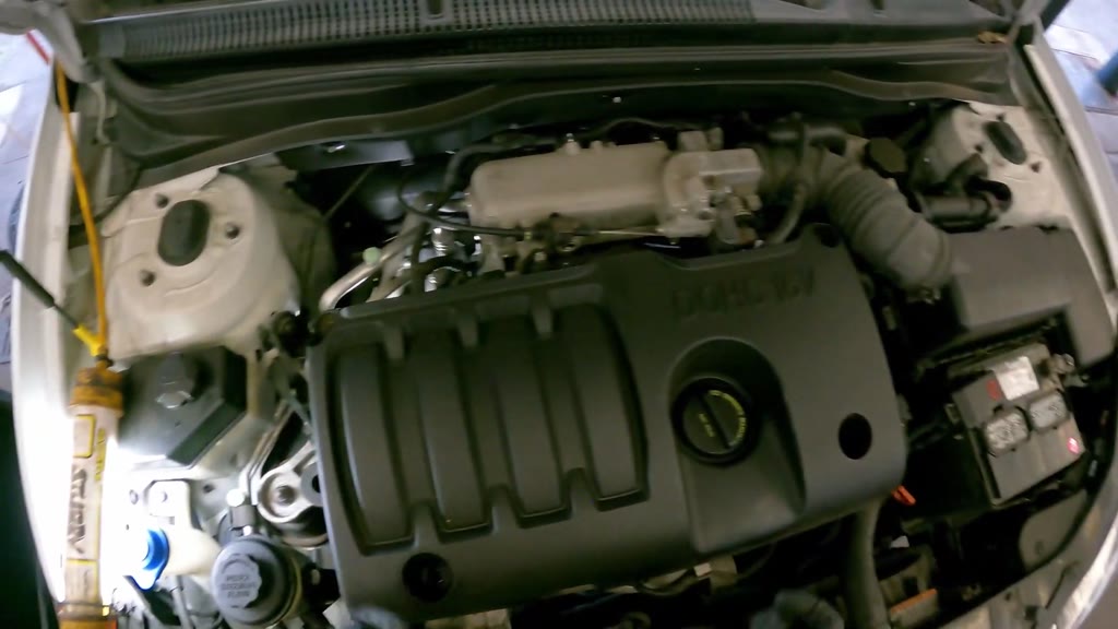
Collect the cover hardware and turn the cover with its lettering upward. Lower it over the engine with the oil-cap opening aligned, adjusting the rear-left edge around the adjacent lines. Hand-start the front-right, rear-left and front-left bolts, then tighten those three attachments with the extended cordless ratchet.
Tools
Cordless ratchetSocketsSocket extensions
Parts
DOHC 16V engine trim coverEngine trim-cover mounting bolts
⚠ Do not trap the adjacent lines beneath the cover.
⚠ Hand-start the bolts before tightening.
Video 52:49
40
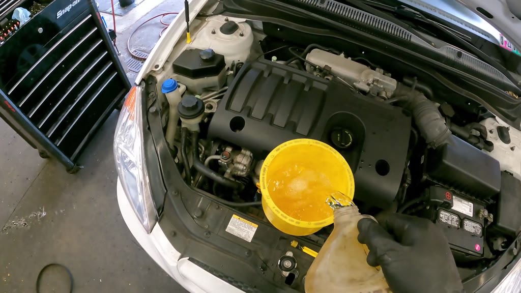
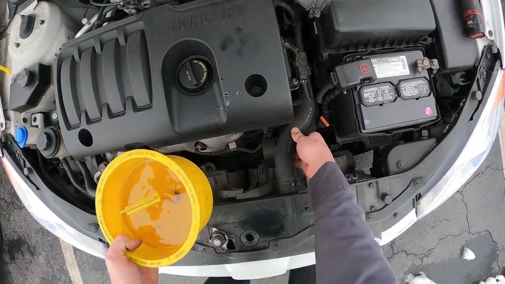
Fit the coolant funnel and begin filling
Time taken 55 s · video 52:03-52:58
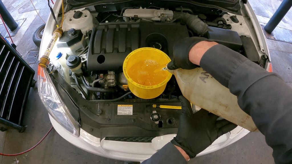
Retrieve the coolant-funnel kit, sort the fittings, and select the yellow adapter, silver retaining cap and long stopper. Seat the adapter in the open filler neck, turn the retaining cap into place, and mount the funnel, leaving the stopper on the radiator support. Retrieve the liquid jug and pour into the mounted funnel with the stream contained inside the bowl.
Tools
Coolant funnel kitLiquid jug
Parts
Cooling-system refill liquid
⚠ Secure the adapter and retaining cap before pouring.
⚠ Keep the funnel stable and avoid spilling refill liquid.
Video 53:45
41
Install the wheel-well splash panel
Time taken 1 min 00 s · video 52:58-53:58
Illuminate and inspect the lower pulley area, then raise the molded splash panel into the opening beneath the surrounding liner. Align the panel and hand-start its two upper mounting bolts. Move the air hose clear, remove and stow the work lights and their leads, then tighten the two panel bolts with the extended cordless ratchet.
Tools
Tube work lightAir hoseCordless ratchetSocketsSocket extensions
⚠ Keep lamp leads and the air hose out of the panel and lift-arm area.
⚠ Align the panel before tightening its bolts.
Video 54:35
42
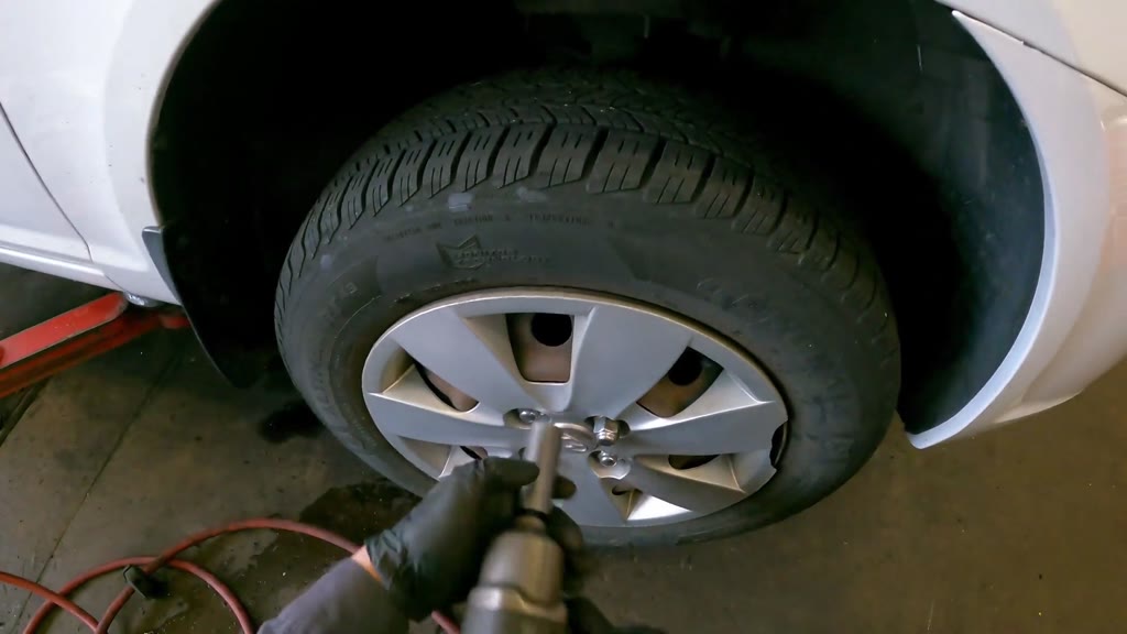
Install the front wheel, wheel cover and lug nuts
Time taken 53 s · video 53:58-54:51
Bring the wheel upright to the hub, align its four holes with the studs, and push it into place. Fit the Hyundai wheel cover with the valve stem and lug openings aligned, then hand-thread all four lug nuts. Fit the long wheel-nut socket to the pneumatic impact wrench and tighten each nut separately while steadying the tire. Draw the air hose away and return the wrench, loose socket and pry bar to storage.
Tools
Pneumatic impact wrenchSocketsAir hoseFlat pry bar
Parts
Timing-side front wheel and tireHyundai wheel coverFront-wheel lug nuts
⚠ Support the wheel while aligning it with the studs.
⚠ Hand-thread each lug nut before powered tightening.
⚠ Do not treat impact-wrench operation as a measured wheel-nut torque check.
Finish filling and check engine operation
Video 55:16
43
Continue filling and clear the working area
Time taken 1 min 17 s · video 54:51-56:08
Refill the jug at the shop bench with the hose-fed dispensing nozzle, then pour the refilled liquid into the mounted coolant funnel. Return loose sockets, extensions, wrenches and other hand tools to their storage, stow the floor cardboard, and place the two removed circular parts on the cabinet worktop. Add a short further pour from the jug into the funnel.
Tools
Liquid jugFluid dispensing nozzleCoolant funnel kitCardboard floor pad
⚠ Clear loose tools and the floor working pad before engine-operation checks.
Video 56:11
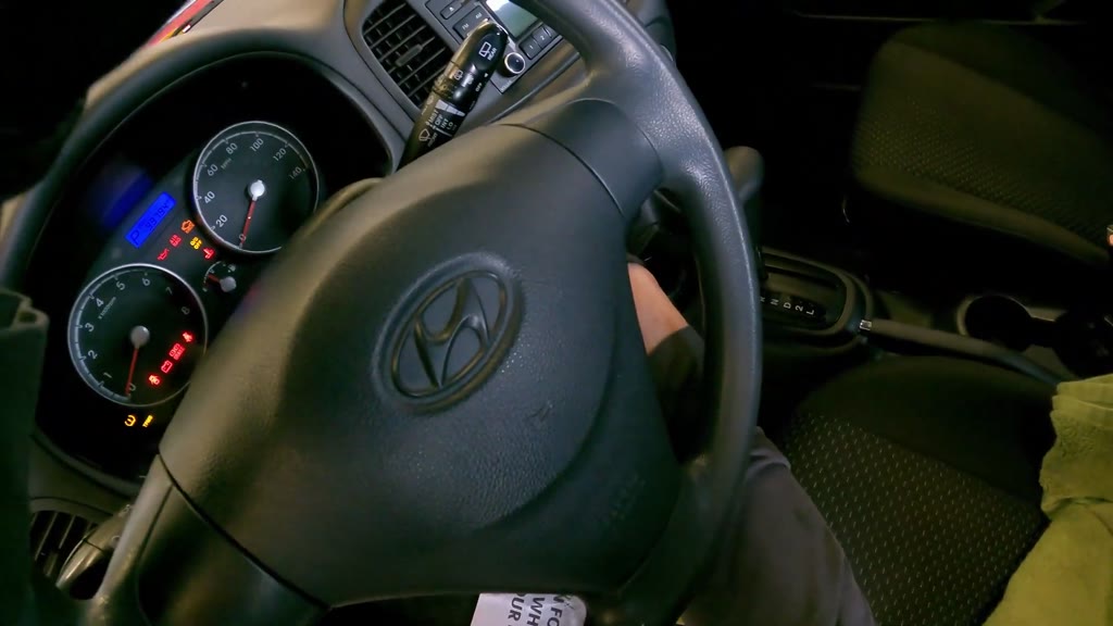
44
Start the engine and observe the coolant funnel
Time taken 17 s · video 56:08-56:25
Open the driver's door and operate the ignition key to start the engine. Check the instrument-cluster warning-light changes and the rising tachometer, then step out and close the door. Return to the front and observe the funnel liquid level, ripples and bubbles without removing the funnel.
Tools
Ignition keyCoolant funnel kit
Parts
Cooling-system refill liquid
⚠ Keep hands, clothing, hoses and tools clear of moving engine-drive parts.
⚠ Keep the funnel fitted during this observation.
Video 56:41
45
Secure the engine-cover bolt beside the intake hose
Time taken 24 s · video 56:25-56:49
Inspect the cover mounting recess beside the intake hose and move the small crossing hose clear. Hand-start the cover bolt, then tighten it with the cordless ratchet, extension and socket. Reposition the small hose along the cover edge after withdrawing the tool.
Tools
Cordless ratchetSocketsSocket extensions
Parts
DOHC 16V engine trim coverEngine trim-cover mounting boltsSmall hose beside the engine-cover edge
⚠ Do not trap the small hose beneath the cover attachment.
⚠ Keep the tool and hose clear of moving accessory-drive parts.
Video 56:55
46
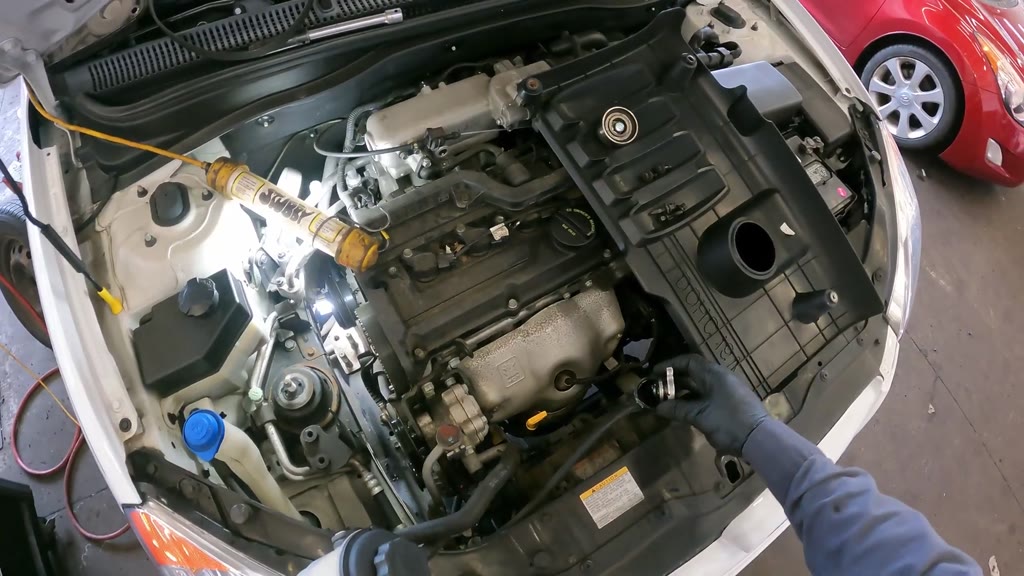
Remove the coolant funnel and reinstall the radiator cap
Time taken 16 s · video 56:49-57:05
Squeeze the upper radiator hose while watching the funnel, then insert the T-handled stopper into the funnel outlet. Lift the plugged funnel from the adapter while retaining its remaining liquid, and turn and remove the adapter and silver retaining cap. Seat the original radiator pressure cap on the filler neck, turn it closed, and inspect the engine bay with the funnel equipment removed.
⚠ Retain the remaining liquid with the stopper before lifting the funnel.
⚠ Handle the funnel and filler fittings carefully to avoid hot-liquid splashes.
⚠ Seat and close the radiator cap after removing the filling fittings.
Service manual
No service-manual parts match for this job. The engine is identified from the car's badge and the 'DOHC 16V' engine cover together with the job title, but the project's manual library holds data-centre service guides only and the manufacturer's shop manual is not openly published. Part names in this guide come from the video alone; check part numbers and specifications (timing marks, belt tension, bolt torques) against the manufacturer's service information.